

TSTN-042
Flatfield Projector Electronics Cabinet#
Abstract#
Description of the electronics cabinet that will be mounted on the dome to power and communicate with the flatfield projector. The Flatfield Projector is a part of the calibration system for the Rubin Telescope. This tech note describes the Flatfield Projector electronics system, requirements, and design. All supporting documentation is included. The electronics system was partially designed by Parker Fagrelius and the design was completed and built by Antanasia Jones in December 2023.
Overview#
In the center of the calibration screen, the Flatfield Projector was installed that includes the optics to project both whitelight (LEDs) and the monochromatic (laser) to the Calibration Reflector and then the Calibration Screen. Since the Flatfield Projector is placed in the center of the calibration screen, there is a very stringent volume restriction on the projector box with a maximum volume of 500mmX500mmX800mm. Since many electronics are needed to power and operate the projector, a separate electronics cabinet for the projector is being utilized and is installed beneat the projector box on the back of the calibration screen.
Initially, the electronics cabinet was going to sit directly below the projector to reduce all cable lengths. Due to access issues, this was not possible. The electronics cabinet is mounted about 3 meters below the projector.
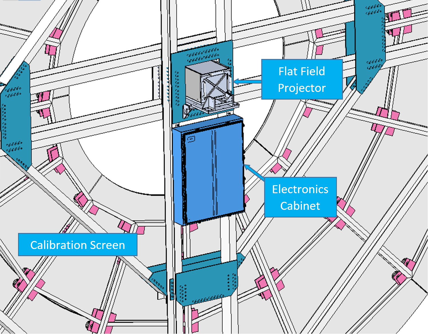
Fig. 1 Initial location of the electronics cabinet#
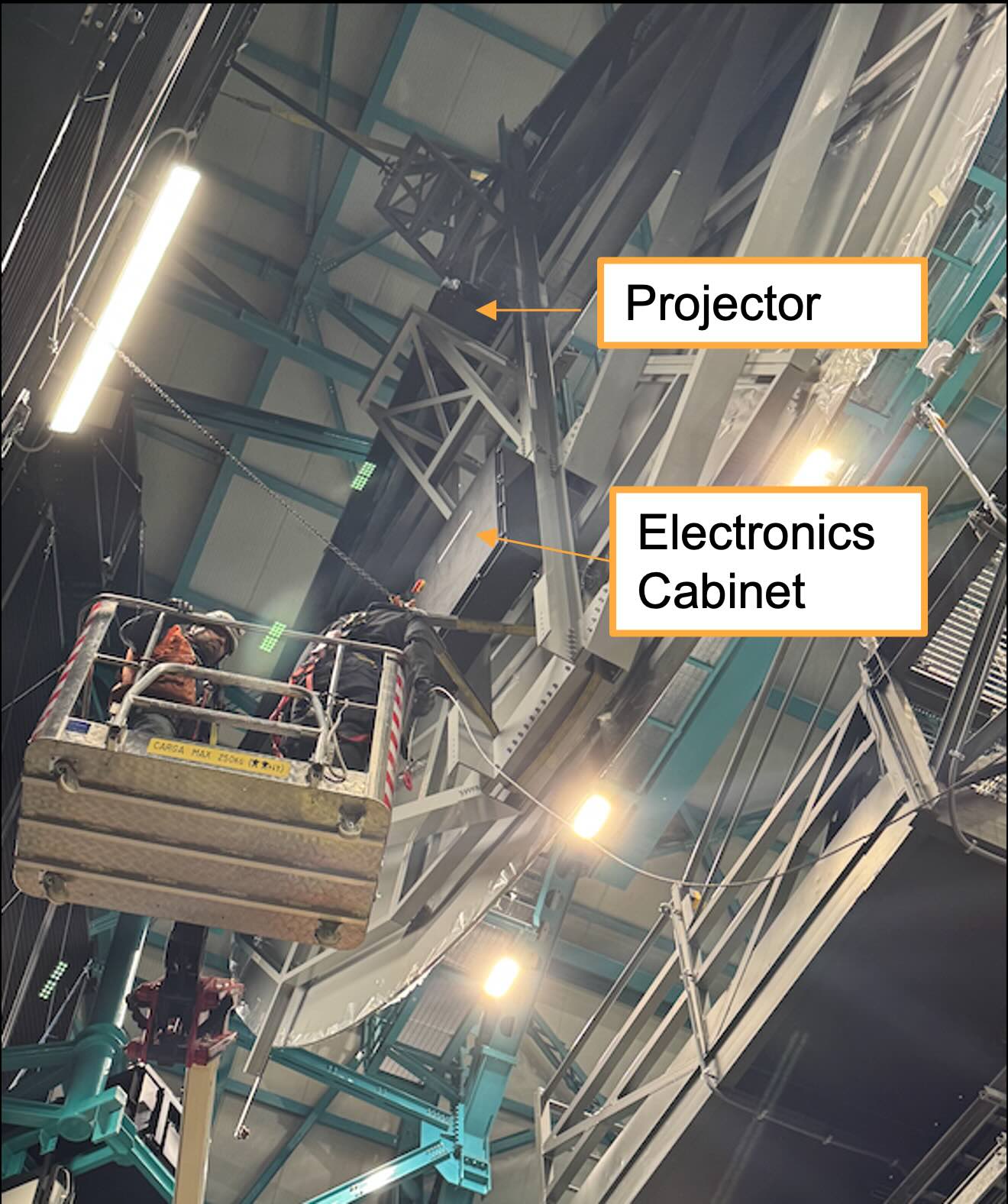
Fig. 2 The view of the projector and the electronics cabinet from behind the calibration screen#
Design#
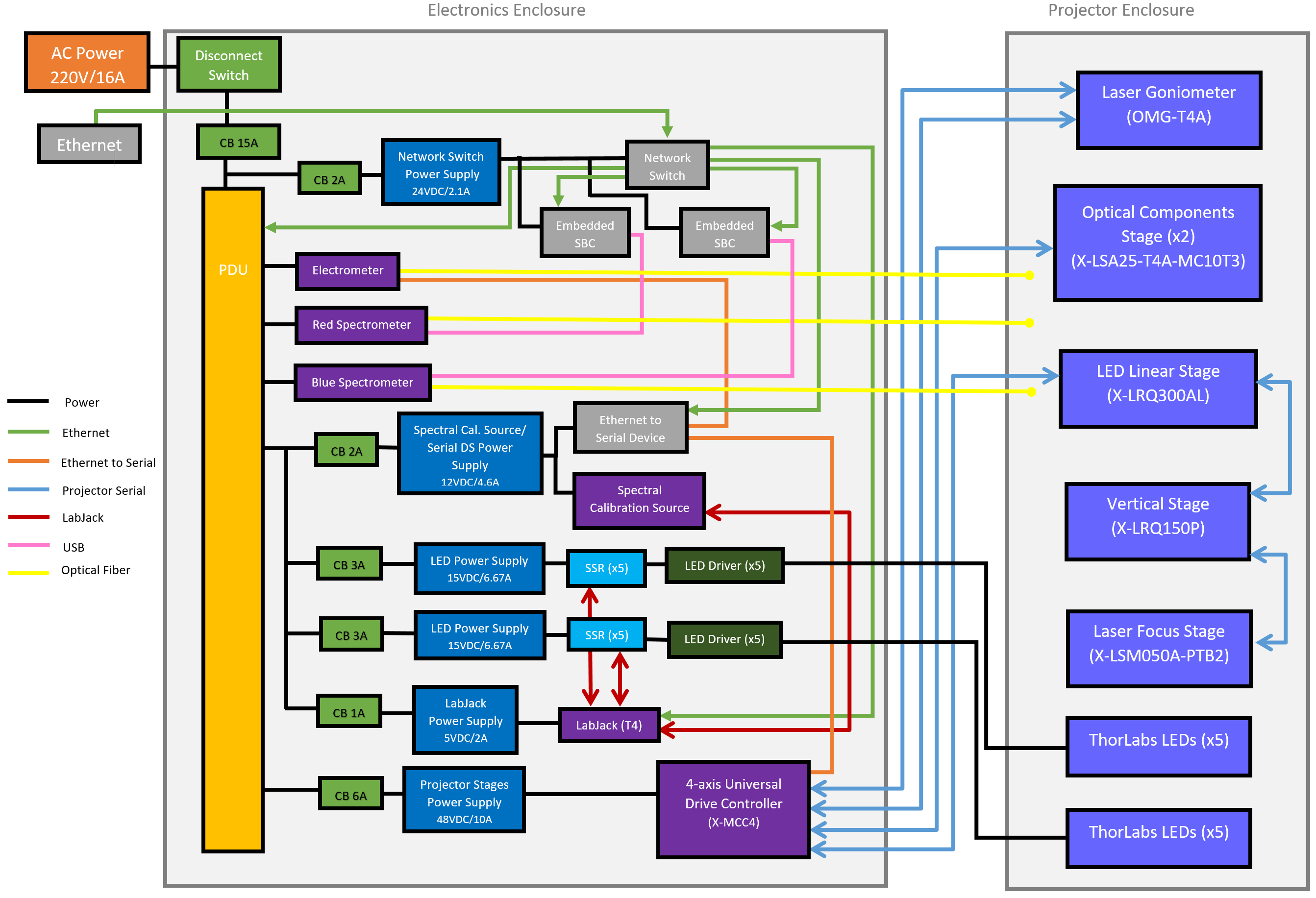
Fig. 3 Block Diagram of the Projector electronics cabinet.#
All design documents for the electronics cabinet can be found in Docushare.
Initial documentation on the design and specifications can be found on Confluence.
Projector Enclosure#
The Flatfield Projector contains the optics for both the LED and laser projectors, as well as the LED assemblies, and some monitoring hardware. It uses linear stages to select between the LED and Laser projectors.
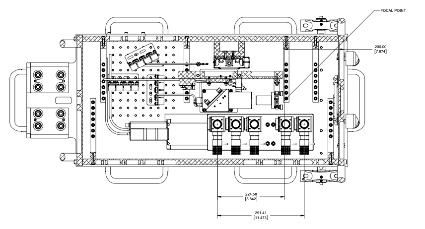
Fig. 4 The projector box looking down from the top. For more informaiton, see TSTN-060.#
The electronics that sit within the projector are:
Light Source Vertical Stage: LRQ150P, Selects between the LED and Laser Projector
Laser Goniometer: OMG-T4A, Gimbal for laser output. Adjusts the tip/tilt of the fiber. Two-axis control via Universal Controller, X-MCC4.
Laser Focus Stage: LSM050A-PTB2, Sets collimation distance as a function of wavelength. Moves collimated lenses relative to the output of the fiber.
LED Linear Stage: LRQ300AL, Enables picking off light from different LED Projectors
LED Focus Stage: LSA25-T4-MT10T3
LEDs: Uses multiple LEDs of varying wavelengths to create a “white light” projector. A dichroic will be used to combine the light from LEDs.
The projector is connected to the projector electronics cabinet via a cable bundle that is routed up the calibration screen structure. This bundle runs ~6m and contains the control cables for all 10 LEDs, 3 cables for the linear stages, a cable for the photodiode and the two fiber optics for the spectrographs.
Electronics Cabinet#
The Electronics cabinet was designed to run on 220VAC, 50Hz, 1 Phase, 16A. The power comes from the Collimated Beam Projector (CBP) Electronics Cabinet due to a limited amount of power outlets available through the contractor. The function of the electronics cabinet is to power and control the central projector electronics (Linear stages, LEDs, etc.) within the projector, and power and control the meters used to monitor the light coming from the projector.
The electronics cabinet must be powered down via a disconnect switch on the door to open the cabinet. Power will be shut down to all the electronics in the cabinet and the central projector when the cabinet is opened.
The Electronics Cabinet includes a PDU, an Electrometer, two Fiber Spectrographs, a Network Switch, an Ethernet to Serial Server, an Embedded SBC, a LabJack, a 4-axis Drive Controller for the Projector stages, ten Solid State Relays, and ten LED Drivers. There are 5V, 12V, 15V, 24V, and 48V AC to DC power supplies that are all powered through the PDU.
Note
Since the Central Projector and electronics will receive power from the CBP electronics cabinet, when the CBP electronics cabinet is down or under maintenance the power to the Central Projector will also be off.
The maximum power, when all the components are operating at full capacity simultaneously, for the entire central projection system was calculated as approximately 730W. The standby power, when the system not in use, but still powered, was calculated as approximately 180W.
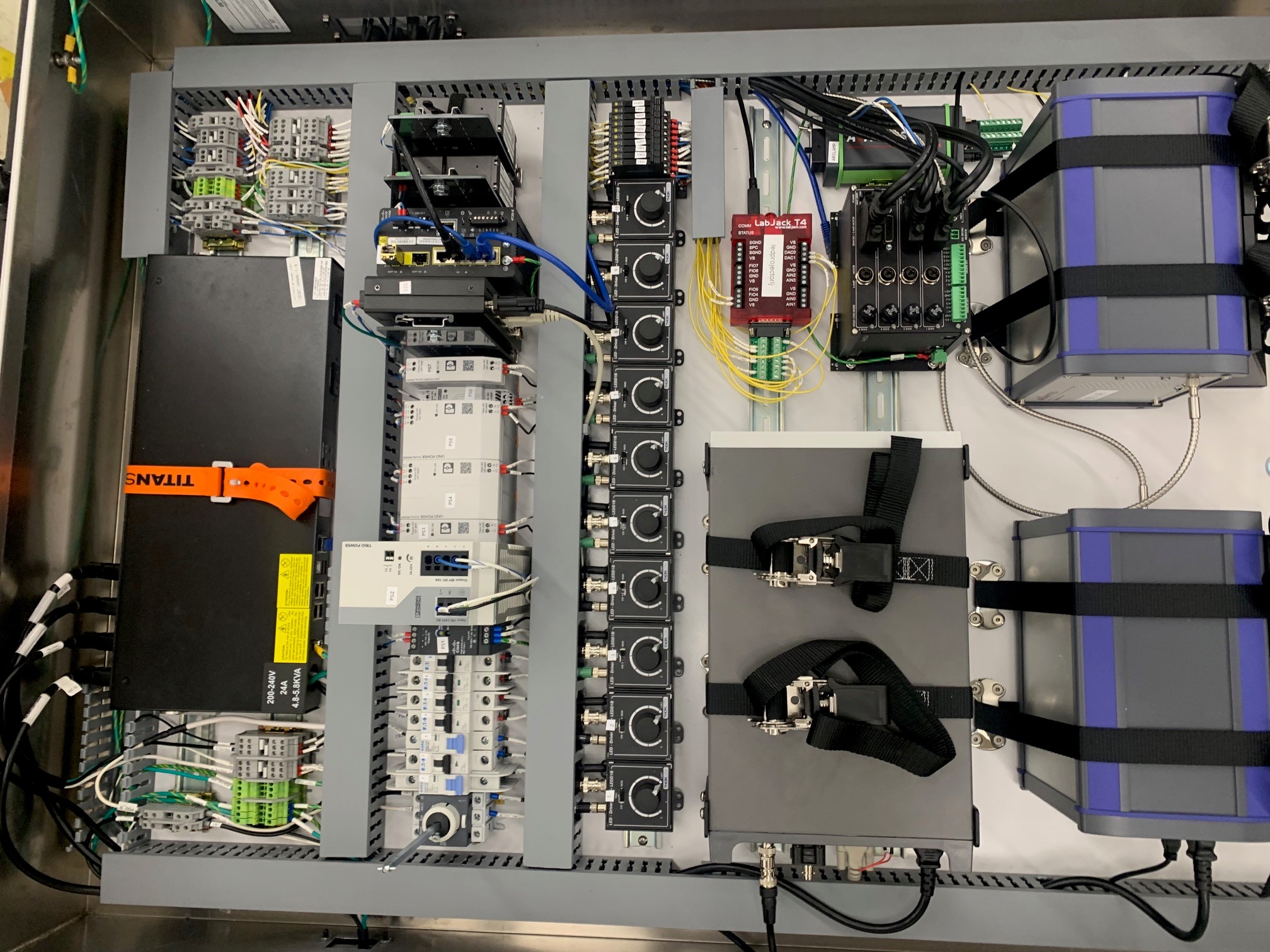
Fig. 5 Picture of the inside of the electronics cabinet panel#
Component Descriptions#
Fiber Spectrographs#
The fiber spectrographs used are an Avantes SenseLine AvaSpecULS2048x64TEC, with a wavelength range of 200-1160 nm. An optical fiber runs from each of the two fiber spectrographs and monitors the light from the spectral output of the light sources, one monitors red light and the other monitors blue light.
The fiber spectrographs are controlled via USB that runs directly from the fiber spectrograph to an embedded SBC in the electronics cabinet. It can be commanded by the ts_fiberspectrograph CSC. More information can be found at https://ts-fiberspectrograph.lsst.io.
Embedded SBC#
The embedded SBCs are ADL1500 Embedded Solutions. Fiber Spectrographs are connected to the SBCs via a USB cable. Due to the USB connections, we have to run the CSC directly on the SBC. Therefore, when we used DDS before Kafka, two network connections to each SBC was required due to the unique comm protocol. Those two ethernet connections are still in place, but one can be replaced now that we are consistently running with Kafka.
Electrometer#
The electrometer used is the Keithley 6517B. It monitors the relative brightness of the light sources in the projector.
The electrometer is controlled via a Serial Device Server, the MOXA Nport 5100.
The electrometer can be run in charge or current mode. The Electrometer is commanded by the ts_electrometer CSC, which has its configuration stored in ts_config_ocs. See the XML documentation for more information.
The electrometer sits in the electronics box and the cable from the photodiode is routed to the Projector enclosure. Information on the electrometer and photodiode can be found on Docushare here
Ethernet-to-Serial Server#
Moxa 5450I-T, 4 port Eth to Serial server. Port 1 is RS232 for communications with the Zaber electronics and port 2 is RS485 communications to the Electrometer. Ports 3 and 4 are reserved for future expansion. Information on the Moxa setup can be found here.
Power Distribution Unit (PDU)#
Power distribution unit is the Raritan PX3-5288R. It can be accessed at pdu1-mainflat-as01.cp.lsst.org (139.229.168.153).
The Network Switch and the Embedded SBCs are NOT powered through the PDU.
Outlet |
Name |
|---|---|
8 |
Blue Spectrograph |
9 |
Red Spectrograph |
10 |
Electrometer |
11 |
Moxa/LabJack/LED Drivers/ Projector Controller & Stages |
LED Drivers#
The LED drivers are the Thorlab LEDD1B T-Cube LED Drivers. These are used to drive power to the LEDs in the projector. The LED Drivers typically will function at max power to operate the LEDs in the projector.
There are ten LED Drivers, each connected to a solid-state relay (SSR). Each SSR is connected to the LabJack, which is programmed to send a signal to the SSR that corresponds with the LED Driver(s)/LED(s) that are to be turned on.
Each LED Driver will be funcitoning in modulation mode, which allows for the LEDs that are selected to be adjusted in brightness. The LabJack is used to send a signal, via a BNC cable, to no more than two LED Drivers at a time (at most two LEDs will be on at a time in the projector).
Arc Lamp#
The spectral Calibration source (arc lamp) is an AVALight-Cal-Mini. Attached to the Arc lamp is a DB15 board to connect the I/O pins to the LabJack, which turn on and off the arc lamp.
LabJack#
This LabJack T4 is used to send signals to the SSRs to switch on and off the LEDs, and sends a signal to the Spectral Arc Lamp to switch it on and off. Connected to the LabJack is a DB15 Board, which allows for extra pins for the ten SSRs to connect to the LabJack.
4-axis Universal Controller#
The Zaber linear stages are controlled via X-MCC4. The OMG-T4A (with two connections) and the LED Linear Stage connect directly to the X-MCC4 with MC10 cables. The remainder are connected via RS-232 and daisy chained together. Zaber electronics include a Laser Goniometer, Optical Component Stage, LED Linear Stage, Laser Focus Stage, and a Vertical Stage.
Ethernet Network Switch#
The installed switch is the Cisco Catalyst IE-3100-8T2S-E 8-Port Ethernet. The Network Switch is powered at all times except when the disconnect switch on the door of the electronics cabinet is ‘OFF’ or power is otherwise lost to the electronics cabinet. A fiber optic is routed directly from the dome switch to this switch.
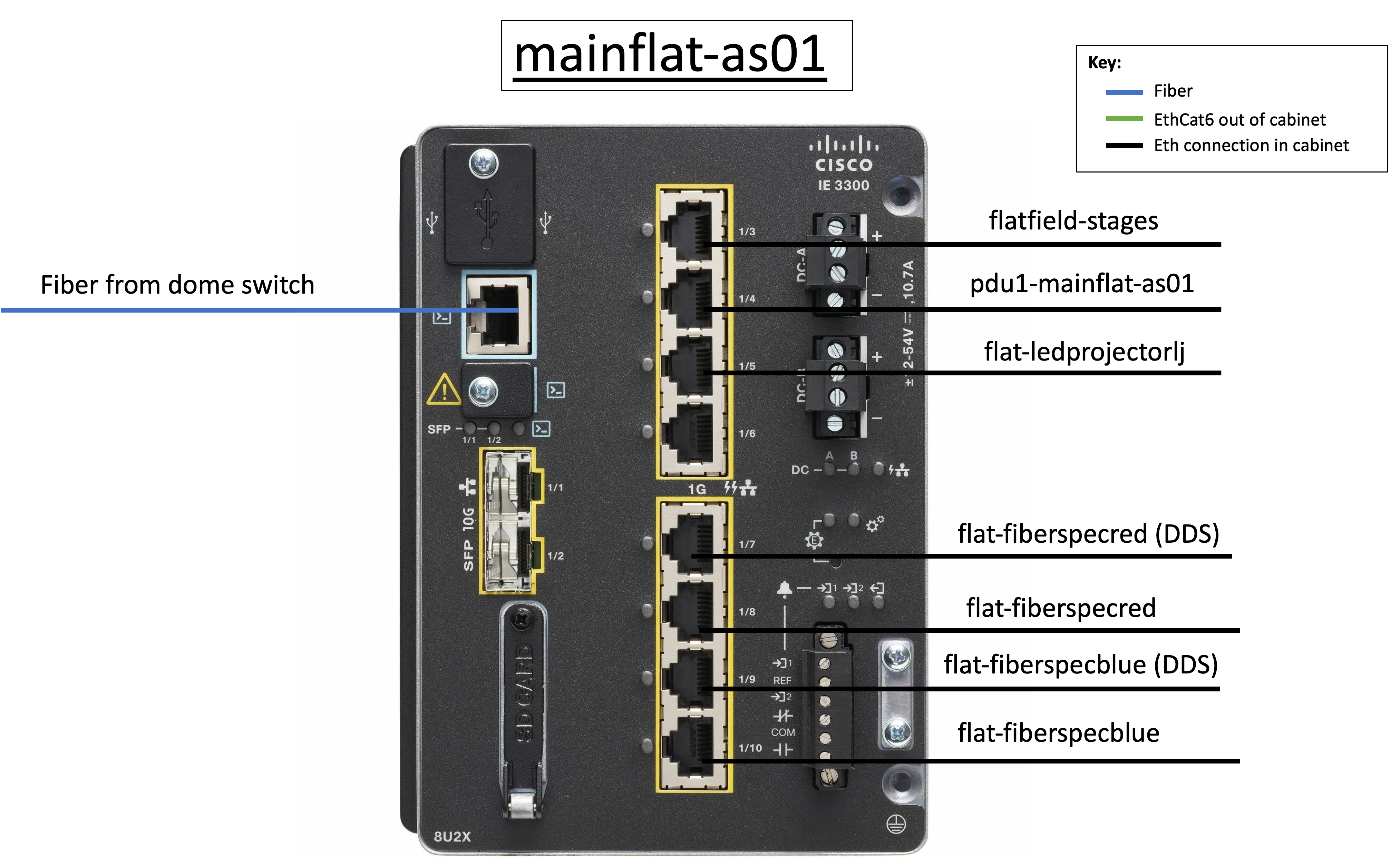
Fig. 6 Setup of the Cisco Network Switch#
Note
The Network Switch does not have enough power for POE.
Component |
MAC address |
DHCP name |
Static IP Address |
|---|---|---|---|
PDU |
00:0d:5d:2f:d8:09 |
pdu1-mainflat-as01 |
139.229.168.153 |
Moxa |
00:90:e8:ba:d4:9b |
flatfield-stages |
139.229.168.154 |
Network Switch |
20:cf:ae:64:5e:a0 |
mainflat-as01 |
10.17.0.98 |
LabJack |
90:2e:87:00:ab:90 |
flat-ledprojectorlj |
139.229.168.155 |
Embedded SBC - Red |
00:01:05:3d:71:57 |
flat-fiberspecred |
139.229.168.156 |
Embedded SBC - Blue |
00:01:05:34:11:3f |
flat-fiberspecblue |
139.229.168.157 |
Electrometer |
80:09:02:0F:CB:E1 |
flat-electrometer |
139.229.168.158 |